STRUCTURAL ANALYSIS
NWTE has produced over
2,000 tower structural analysis reports.
A structural analysis is
performed when changes to a tower’s appurtenance configuration
are made. It is common for tenants on a tower to require
replacement of existing antennas and/or placement of additional
antennas, associated radio equipment and feed lines, thus
increasing the amount of wind load and weight to be supported by
the tower. Each tower is evaluated per the requirements of the
TIA-222-G or TIA-222-H Standard, “Structural Standards for Steel
Antenna Towers and Antenna Supporting Structures,” depending on
which revision is currently adopted by the jurisdiction.
NWTE uses tnxTower (Tower
Numerics, Inc.)—a sophisticated software program—to perform each
structural analysis. The program allows the engineer to build
finite element models of guyed and self-supporting towers and
monopoles. The engineer inputs tower geometry, structural member
sizes and materials, guy wire information, connection data,
appurtenance information, wind speed and ice thickness. The
program calculates and applies wind and ice loads in the model.
Program output includes structural member and guy wire forces
and capacities, tower deflections, and foundation loads.
NWTE determines if
structural member forces, deflections (if microwave antennas are
installed), and foundation loads are within the allowable limits
per the Design Standard. NWTE then issues a structural analysis
report which includes tower elevation and plot plan sketches
showing structural member and guy wire sizes, an appurtenance
list, a cross section sketch showing locations of feed lines, a
list of structural member forces and capacities, and
recommendations, if any, for strengthening the tower. NWTE can
also provide construction drawings for tower structural
modifications.
Typical graphical output
from tnxTower is shown below.
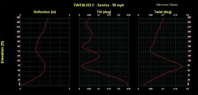
Figure 1: Guyed tower
deflections.
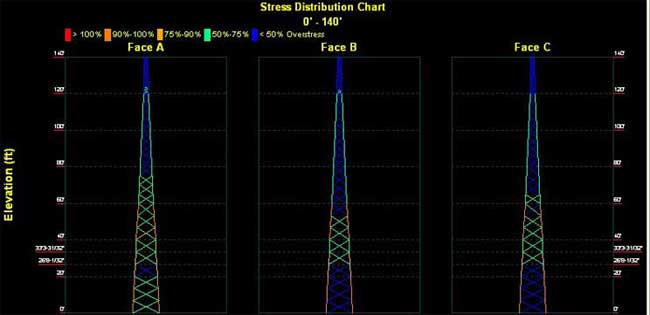
Figure 2: Structural
member demand–capacity ratios.
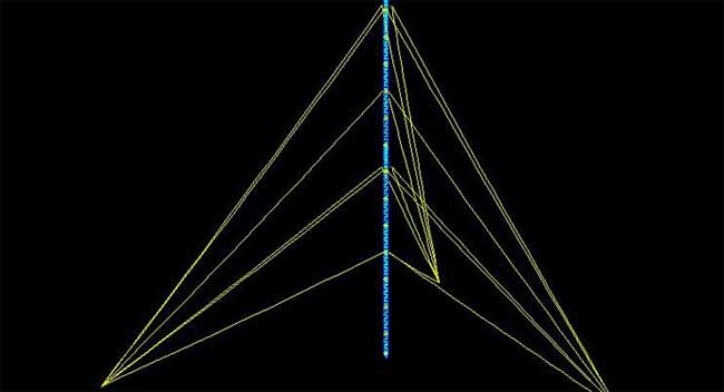
Figure 3: Guyed tower
isometric view.